— Reliability System — Setup Health Monitoring — Software Component Status —
Setup Health Monitoring
Software Component Status
To monitor the health of the DETEXI software components (services) you need to assign
a task (
action/notification that will be executed in a case of failure) to each component you wish to monitor.
Setup NVR Components Health Monitoring —
- In the NVR Control Center go to the Monitor
- Press Health monitor On/Off button in the bottom right corner — the system health monitor No answer task panel appears.
- To assign a task to the component select previously created task from the drop-down list next to the component.
- Assign a task to each system component you wish to monitor.
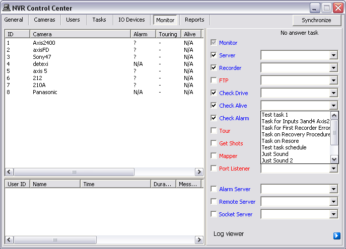
- Component failure if any will be detected within 3 minutes and the assigned task will be executed.
- System will check status only for the components with the checkbox checked.
|
The underlying structure of the DETEXI NVR software consists of many individual services, which allow execute and organize all the tasks it is responsible for. The services are registered with Windows as Services; some are configured as
automatic by default. All services are visible and configurable in the
NVR Control Center — Monitor.
Knowing the responsibility of each service is important. This allows users to make sure the necessary services for the given application are running and controlled properly, while unnecessary services are turned off to preserve system resources.
- Monitor — Also known as the Startbar, is an internal service to start/stop other NVR services. The Monitor service is also responsible for monitoring the health and status of all NVR Services.
- Server — Also known as the CamServer, authenticates remote users connected to the NVR through the Remote Client. The CamServer is also responsible for tracking statistics about the remote user’s connections.
- Recorder — Records information and images from each video input into the NVR archive, according to the configured schedules, preferences, alarms and events.
- FTP Server — Receives images from cameras via FTP (if configured) and writes them into the NVR archive. It also raises an alarm when such images are received from a camera, and can also be used for FTP notification of IP address changes from the camera to the NVR.
- Check Drive — Monitors the condition of the storage path and device to confirm existence and available space for new video being recorded to the archive.
- Check Alive — Monitors if camera is online and video inputs are active.
- Check Alarm — Monitors the hard inputs of connected video devices, and raises alarms when defined changes are seen on such inputs.
- Tour — Moves PTZ cameras through a predefined series of locations according to defined schedules or on alarms or events.
- Get Shots — Captures still shots related to alarms from streaming video when configured, and stores them in a special location in the archive.
- Port Mapper — Also known as the Port Mapper. When configured, the Port Mapper routes network requests between two network connections on different subnets or networks. This allows for separate security and corporate networks across which the DETEXI system can communicate.
- Port Listener — Also known as the I/O Listener, has the ability to monitor alarms raised by local alarm devices connected to the NVR computer via COM ports.
- Alarm Server — Also known as Alarm Central, is responsible for raising alarms via the Text-to-Speech engine, telephone, e-mail and other mediums. This is configured as an Automatic Windows Service and starts at Windows startup.
- Remote Server — An internal service for intercommunications between linked NVR Domain Controller and child NVRs. This is configured as an automatic Windows Service and will start with Windows.
- Socket Server — An internal service to support remote TCP/IP access to the NVR. This is configured as an automatic Windows Service and starts at Windows startup.
— Reliability System — Setup Health Monitoring — IP-Device Status —
Setup Health Monitoring
IP-Device Status
The DETEXI NVR streaming and records video information from the
IP-cameras/video servers, which are complex devices by themselves and can often be the source of problems.
There are two methods to deal with IP-devices errors —

Using the
Check Alive program
Using a
Recovery Procedure in the IP-device
Recording Schedule
- Check Alive
- Recovery Procedure
- Recommended Settings
- Create Template
Setup Actions on Alarm for the Camera Using Check Alive Program —
The Check Alive program is relatively heavy on NVR resources and it should be used only in the case of recording on I/O ports when the recorder is off and starts to record when the signal from I/O port is received.
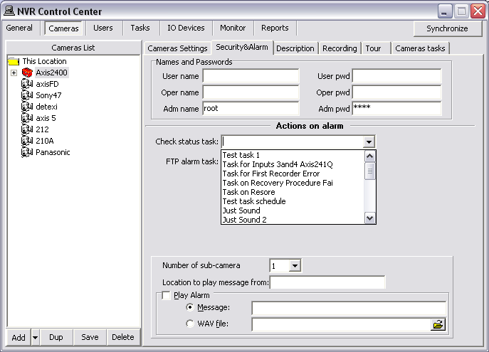
- In the NVR Control Center — Cameras select a camera from the Cameras List.
- Switch to the Security & Alarm.
- Under Actions on alarm select an appropriate predefined task from the Check status task drop-down list.
Task initiates if the IP-device fails to answer on Check Alive request.
- Repeat steps 1-3 for any camera from the Cameras List to setup actions on alarm task.
- It must be clear for you that if a device fails to answer this does not necessarily mean that there is a physical device failure. It could be a connection (network) error. From the NVR reliability point of view it is irrelevant as to why there is no video stream but from the point of view of the technician (who has to fix the problem) there is a big difference.
|
Setup Recovery Procedure in a Camera Recording Schedule —
Another method to deal with IP-devices errors is to setup Recovery Procedure inside a camera Recording Schedule. The Recovery Procedure fully describes how the Recorder will deal with the faulty camera.
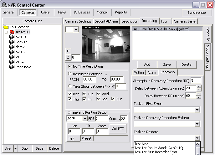
- In the NVR Control Center — Cameras select a camera from the Cameras List.
- Go to the Recording and switch to the Schedule side tab.
- Select a schedule from the Schedule list to update an existing schedule settings or press Add button below the Schedule panel to create a new schedule.
- Switch to the Recovery tab to setup a Recovery Procedure parameters (if the Recovery Procedure Template was created a newly created schedule will use the template parameters as default) —
Attempts in Recovery Procedure (RP) — recommended 5;
Delay Between Attempts (in sec) — recommended 30;
Delay Between PR (in sec) — recommended 60;
- Select predefined tasks for events you are going to track (in any combination)—
Task on First Error — (if assigned) the Recorder initiates the corresponding task immediately on the video stream failure;
Task on Recovery Procedure Failure — (if assigned) task initiates if all the attempts of Recovery Procedure have failed;
Task on Restore — (if assigned) task initiates in case the IP-device comes back online.
- Press Save button below the Schedule panel.
- Repeat steps 3 - 6 for the other schedules.
- Setting up a Recovery Procedure for many cameras with complicated recording schedules could be time consuming. To make it easier use the Recorder Recovery Settings Template.
|
The Recovery Procedure Recommended Settings —
Attempts in Recovery Procedure (RP) — 5;
Delay Between Attempts (in sec) — 30
Delay Between PR (in sec) — 600
Task on First Error — assigned
Task on Restore — assigned
According to the recommended settings the Recorder initiates the Task on First Error when the video stream failure occurs. Than makes up to 5 attempts with 30s interval to recover the stream. If any of the attempts succeeds the Task on Restore notification / action will be initiated; if not — the next round of attempts to connect to the faulty camera starts in 10min (600s).
- Setting up a Recovery Procedure for many cameras with complicated recording schedules could be time consuming. To make it easier use the Recorder Recovery Settings Template.
|
Create Template for Setting a Recovery Procedure —
Setting up a Recovery Procedure for many cameras with complicated recording schedules could be time consuming. To make it easier a template enforcing particular settings in a newly created schedule can be created.
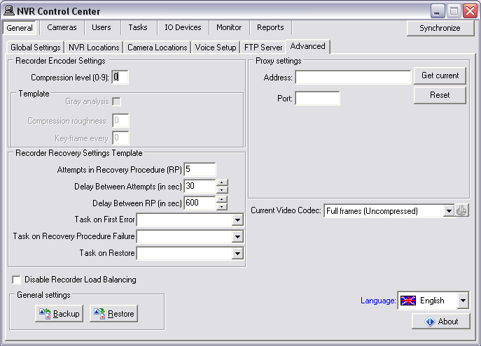
- In the NVR Control Center go to the General — Advanced.
- Under the Recorder Recovery Settings Template setup recovery settings —
Attempts in Recovery Procedure (RP) — recommended 5;
Delay Between Attempts (in sec) — recommended 30;
Delay Between PR (in sec) — recommended 60;
- Select predefined tasks for events you are going to track (in any combination)—
Task on First Error — (if assigned) the Recorder initiates the corresponding task immediately on the video stream failure;
Task on Recovery Procedure Failure — (if assigned) task initiates if all the attempts of Recovery Procedure have failed;
Task on Restore — (if assigned) task initiates in case the IP-device comes back online.
The Recovery Procedure settings from this template will be forced in to each newly created schedule and could be changed.
|
— Reliability System — Setup Health Monitoring — NVR Catastrophic Errors —
Setup Health Monitoring
NVR Catastrophic Errors
There are some problems that should not be tolerated. If the tasks associated with them are initiated you have to seriously reconsider your NVR settings and/or the hardware you are using.
The
Writing error task initiates when the
Recorder fails to record streaming data on the hard drive. It could be because of a
hard drive error, a
Windows error or the Recorder could not do its job because of
lack of resources (usually an underpowered CPU).
The
Drive limit reached task initiates in case of free space for the system files or free space necessary for NVR functioning becomes too low. In some circumstances the
Recorder service could even be stopped because the NVR cannot manage the given amount of information due to a
lack of system resources. In this case you should reconsider your IP-devices
Recording Schedule settings and /or
Keep information for parameter and/or your
hardware configuration.
In order to get advantage of getting notification/action in case of any of the catastrophic errors occurs you
must setup the
Writing error and
Drive limit reached tasks.
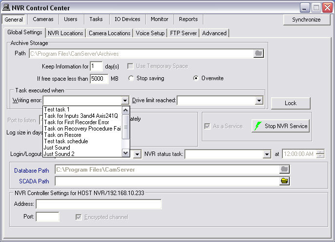
Setup Catastrophic Errors Tasks —
- In the NVR Control Center go to the General — Global Settings
- Under the Tasks executed when select an appropriate predefined task from the Writing error drop-down list and the Drive limit reached drop-down list.
|
— Reliability System — Setup Health Monitoring — NVR Status Task —
Setup Health Monitoring
NVR Status Task
The purpose of the
NVR Status task is to send out the current NVR status of the NVR components at predefined time.
The
NVR Status Task is initiated
once a day at a predefined time and provides the user a list of the NVR components being monitored and their status.
Setup NVR Status Task
- In the NVR Control Center go to the General — Global Settings
- Select an appropriate predefined task from the NVR status task drop-down list.
- Set a desired time.
- If you want to setup your own schedule with a different time interval (twice a day or once a week or whatever you want) to send out notification that the NVR is alive, you should create a Scheduled Task and use it for checking if the Reliability System is functioning properly.
|
— Reliability System — Setup Health Monitoring — Child NVR Status —
Setup Health Monitoring
Child NVR Status
Although every NVR in the
NVR Domain Controller configuration should have its own reliability settings there is a new intercommunication layer between the
NVR Domain Controller and a
child NVR, which could also fail and therefore the system administrator must be able to check its status.
To be aware weather all child NVRs are
alive and properly respond to the NVR Domain Controller you should setup the
Task when NVR does not respond for
each child NVR in the NVR network (domain).
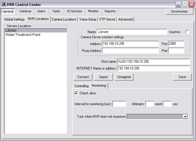
Setup Child NVR Status Task
- In the Domain Controller NVR Control Center go to the General — NVR Locations.
- Select a child NVR from the Servers Locations list.
- Switch to the Monitoring tab and input your setting to define an Interval for monitoring (sec), number of Attempts and interval between them.
- Select an appropriate predefined task from the Task when NVR does not respond list.
- Check Check alive check box.
Recommended Settings —
Interval for monitoring (sec) — 300
Attempts — 3
Each (in sec)— 60
- If you know for a fact that the site is temporarily down for maintenance or other issues, simply uncheck the Check Alive check box.
In this case the system will NOT initiate unnecessary tasks for a known problem and will return to monitoring only after you check the box again.
|


 DETEXI® Network Video Management System