— Network Options and Setup — Dual LAN —
Network Options and Setup
Dual LAN
This network configuration, consisting of a Security LAN separate from the existing Corporate LAN, is the preferred configuration for most IP Surveillance Systems. This allows the security network traffic to be separated from the normal corporate network traffic, so each network can do its job efficiently.
The diagram shows such a configuration without being exposed to the Internet. One could expose the Security LAN to the Internet by applying the information explained in the Single LAN and Internet section.
In this type of network configuration, all cameras reside on the Security network, and clients can reside on both. The DETEXI NVR acts as a common point directing traffic and controlling bandwidth use between the two. This requires two network cards in the NVR box so that it has an IP address in the Corporate network as well as an IP address in the Security network. Using the NVR Port Mapper, the NVR will act similar to the router in the Single LAN & Internet configuration.
|
— Network Options and Setup — Dual LAN — Required Camera Setup —
Network Options and Setup
Dual LAN
Required Camera Setup —
Each camera must be setup properly in order to see the router as its gateway to the Corporate LAN. This can be done through the HTML interface provided by the camera.
Depending on the camera, the location of the settings will be slightly different but they will typically be found in the Network or LAN settings in the camera.
- The Subnet Mask should be set to 255.255.255.0 (as typical)
- The Default Router or Default Gateway should be set to the Security IP address of the NVR — 192.168.100.100 in the diagram.
|
— Network Options and Setup — Dual LAN — Required NVR Setup —
Network Options and Setup
Dual LAN
Required NVR Setup —
- Define external IP address
- Start Port Mapper service
Define external IP address
The NVR must now hold the information for two different connection paths for each camera — one to hand off to clients in the Security LAN, and one to hand off to clients in the Corporate LAN.
In this example, the Security IP 192.168.100.100 is the internal address and the Corporate IP 10.1.100.100 is the external address.
In each camera definition, define IP addresses and their appropriate ports —
- In the NVR Control Center go to Cameras — Cameras Settings.
- Choose a camera from the Cameras List.
- Select Use as External Address from the Proxy Type drop-down list.
- Type both IP address and port number into Proxy input fields.
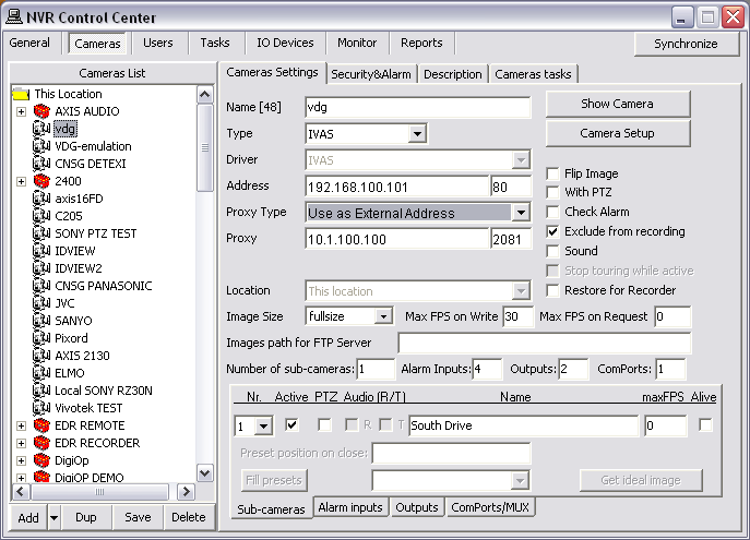
Each camera would be configured similarly —
| Camera |
Internal IP address |
External IP address |
| IP |
Port |
IP |
Port |
| 1 |
192.168.100.101 |
80 |
10.1.100.100 |
2081 |
| 2 |
192.168.100.102 |
80 |
10.1.100.100 |
2082 |
| 3 |
192.168.100.103 |
80 |
10.1.100.100 |
2083 |
|
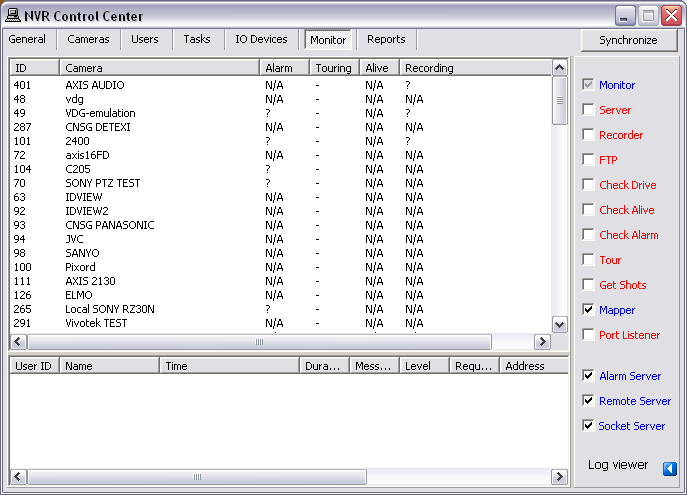
Start Port Mapper Service
The Port Mapper service must also be running. To start the service —
- In the NVR Control Center go to Monitor.
- Click on the Mapper link (it will show blue when the service is running) or check the Mapper checkbox — Monitor service will automatically start the Port Mapper with the NVR.
When the Port Mapper is running, an icon will show in your System Tool Tray.
|
— Network Options and Setup — Dual LAN — Required Port Mapper Setup —
Network Options and Setup
Dual LAN
Required Port Mapper Setup —
- Use Cameras database for mapping
- Mapping ports for the NVR and Archiving
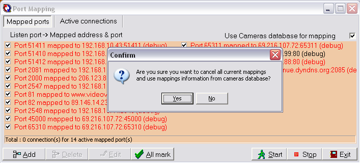
Use Cameras Database for Mapping
The Port Mapper must be configured to enable communications to the cameras and the NVR on the Corporate IP address. Because we have already configured the camera definitions in the NVR Control Center to have both IP addresses and ports, we can tell the Port Mapper to create a configuration based on these settings.
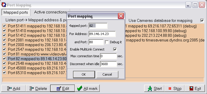
- Double-click on the Port Mapper icon in the System Tool Tray and go to Mapped Ports.
- Enable the Use Cameras database for mapping checkbox to create a configuration based on the camera settings in the NVR Control Center.
- When asked to confirm, click Yes .
|
Mapping ports for the NVR and Archiving
Now, ports must be mapped for the NVR and the Archiving —
- Click the Add button to add a port mapping configuration.
- Create three ports as shown in the following table, each with a 300 sec Disconnect when idle timeout.
| Mapped Port |
For Address |
and Port |
| 2080 |
192.168.100.100 |
2080 |
| 60000 |
192.168.100.100 |
60000 |
| 60001 |
192.168.100.100 |
60001 |
- Check them to enable, and click Start (the port configurations will turn red when running}.
|
— Network Options and Setup — Dual LAN — Required Client Setup —
Network Options and Setup
Dual LAN
Required Client Setup —
Finally, the DETEXI Clients must be configured to know which IP address to use when connecting to the NVR and requesting camera information. Only the clients on the Security LAN need changes.
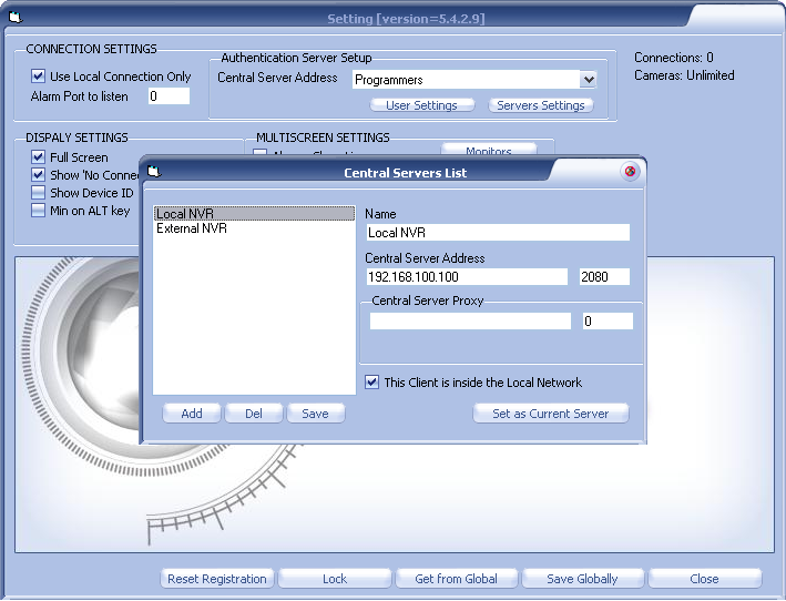
- In the DETEXI Client Settings page under the Authentication Server Setup press Servers Settings button.
- Press Add button and enter any meaningful NVR name into Name field and IP address / port into Central Server Address input fields.
- Check the This Client is inside the Local Network checkbox.
- Press Save button and restart the Client for the changes to take effect.
- Since the Recorder acts as a Client, this must be set in the recording configuration for each camera being recorded in the NVR Control Center also.
|


 DETEXI® Network Video Management System