— Configure Camera Inputs/Outputs —
Configure Camera Inputs/Outputs
A unique feature to network cameras and video encoders, in comparison with analog cameras, is their
integrated input and output (I/O) ports. These ports enable a network video product to connect to external devices and enable the devices to be manageable over a network.
- For example, the DETEXI NVR can be instructed to receive video only when the sensor triggers.
- Or a network camera or video encoder connected to an external alarm sensor via its input port can be instructed to FTP video out to the DETEXI NVR FTP Server.
The range of devices that can connect to a network video product’s input port is almost infinite. The basic rule is that any device that can
toggle between an open and closed circuit can be connected to a network camera or a video encoder.
The main function of a network video product’s output port is to trigger external devices, either automatically or by remote control from an operator or a software application.
- Network camera or video encoder inputs/outputs must be defined in the NVR Control Center — Cameras — Cameras Settings for the NVR to be aware of external devices connected to the IP device inputs/outputs.
- Be sure also that the NVR input/output settings make sense considering the IP device specification.
- External Devices on Inputs
- External Devices on Outputs
Examples of external devices that can be connected to the IP device Input Port
Device Type |
Description |
Usage |
Door contact |
Simple magnetic switch that detects the opening of doors or windows |
When the circuit is broken (door is opened), the NVR can take action by sending full-motion video and notifications |
Passive infrared detector (PIR) |
A sensor that detects motion based on heat emission |
When motion is detected, the PIR breaks the circuit and the NVR can take action by sending full-motion video and notifications |
Glass break detector |
An active sensor that measures air pressure in a room and detects sudden pressure drops (the sensor can be powered by the camera) |
When an air pressure drop is detected, the detector breaks the circuit and the NVR can take action by sending full-motion video and notifications |
Examples of external devices that can be connected to the IP device Output Port
Device Type |
Description |
Usage |
Door relay |
A relay (solenoid) that controls the opening and closing of door locks |
The locking/unlocking of an entrance door can be controlled by a remote operator (over a network) using Remote DETEXI Client |
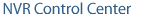
Siren |
Alarm siren configured to sound when alarm is detected |
The NVR can activate the siren when motion is detected either using the built-in VMD or using information from the digital input |
Alarm/Intrusion system |
An alarm security system that continuously monitors a normally closed or open alarm circuit |
The network video product can act as an integrated part of the alarm system that serves as a sensor, enhancing the alarm system with event-triggered video transfers |
— Configure Inputs/Outputs — Configure Camera Inputs —
Configure Inputs/Outputs
Configure Camera Inputs
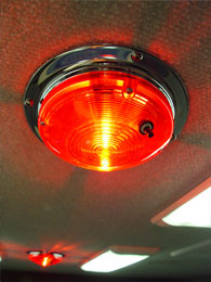
To configure camera inputs connected to external devices —
- In the NVR Control Center — Cameras select camera to configure from the Cameras List.
- In the Cameras Settings enter the number of connected inputs in the Alarm Inputs field.
- Switch to the Alarm Inputs bottom tab — the Input Number drop-down list will automatically be populated with the number of inputs defined.
- Select Input Number from the list to configure the device connected to this input.
- Enter a descriptive Name.
- Select a Normal Status radio button — Open or Closed — indicating whether the input is connected as normally open or normally closed.
- If you are not sure, click the Check Current Status to query the status of the input port.
- If, for instance, the status returns as Open, and the device is not in the alarm state, then the normal status should be set to Open.
- Repeat steps 4-7 to configure all external devices connected to the camera or video server input ports.
- Be sure that the NVR input settings make sense considering the IP device specification.
- Check the documentation of the camera or video server for information on which ports on the terminal block are associated with which inputs.
— Configure Inputs/Outputs — Configure Camera Outputs —
Configure Inputs/Outputs
Configure Camera Outputs
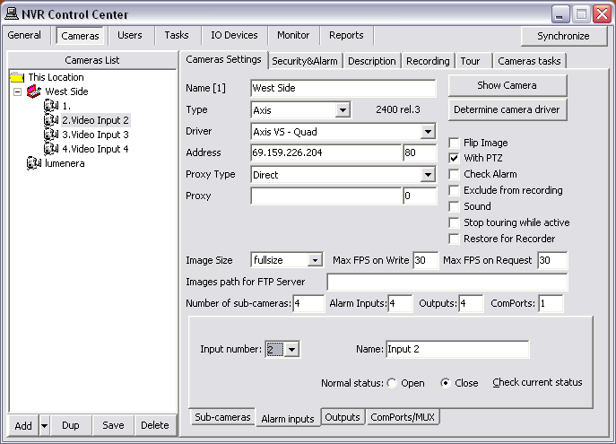
IP-device outputs can be configured with
toggle and/or
momentary behavior.
- With toggle behavior, the state is simply switched indefinitely (i.e. unlock door strike, lock door strike).
- With momentary behavior, the output is set to the non-normal state for a period of time before being returned to the normal state (i.e. unlock door strike for 3 seconds; then return to locked).
- If both options are configured, either action can be taken by the operator or task — each will have their own action button in the DETEXI Client.
- Configure Camera Outputs
- Customize Relay Action Button
- Control Relay
To configure camera outputs connected to external devices (relays) —
- In the NVR Control Center — Cameras select camera to configure from the Cameras List.
- In the Cameras Settings enter the number of connected outputs in the Outputs field.
- Switch to the Outputs bottom tab — the Output Number drop-down list will automatically be populated with the number of outputs defined.
- Select Output Number from the list to configure the device connected to this output.
- Enter a descriptive Name.
- Select a Normal Status radio button — OFF or ON indicating whether the output is connected as normally OFF or normally ON.
- To select a relay type under the Behavior check the Toggle and/or Momentary checkbox. The selected relay type Action button activates.
- Similar relay Action buttons will be available on the DETEXI Client’s camera live view allowing for external devices (relays) to be triggered.
- To customize a relay Action button click on it to launch the Relay Types dialog.
- The default off-delay for momentary behavior is 3 seconds.
- Under the State on Close check proper checkbox — Unchanged , ON or OFF.
- For instance, if the device is a door strike that should always stay locked, the state on close OFF may be desired to prevent from accidentally leaving the door open.
- Repeat steps 4-8 to configure all external devices connected to the camera or video server output ports.
- Be sure that the NVR output settings make sense considering the IP device specification.
- Check the documentation of the camera or video server for information on which ports on the terminal block are associated with which output numbers.
Customized relay
action buttons are important for systems using many different types of external devices connected to cameras and/or video servers outputs: door strikes may work best with 8 second activation, where alarm sounding devices (horns or bells for instance) should be activated for only 3 seconds perhaps.
Customized relay action buttons allow also for intuitive control for users.
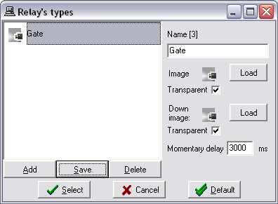
How to configure a customized relay
action button —
- In the Relay Types click the Add button to add a new relay action button.
- Enter a descriptive Name.
- Click Load buttons to download images for the normal and down positions of the button.
- Images must be either 24 x 24 px BITMAP files (24-bit) or 16 x 16 px ICO files.
- A few icons of this type are available on the installation CD in the Utilities/NVR Output Icons directory.
- Check the Transparent checkbox to convert BITMAP image to have a transparent background.
- Top-left pixel color is considered as a background.
- For momentary relay types, define a custom momentary delay (ms) before the output is turned back off.
- Click Save button to save a new relay action button.
- Select a relay action button for use from the list and click Select button.
- Click Cancel button to return without changes.
- Click Default button to return to default settings.
After an IP device outputs were defined in the
NVR Control Center — Cameras — Cameras Settings they are ready for use in
tasks triggered by alarms/events, or manually by operators in the DETEXI Client.
- Relay Action buttons will be available on the DETEXI Client’s camera live view allowing for external devices (relays) to be triggered.
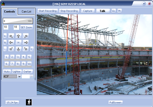
- The momentary relay only has been enabled for the output — only one relay action button is visible.
- If multiple outputs are connected to and configured on the camera, a drop-down list to choose the output number from will be available. When an output number is chosen, the configured control buttons will be displayed for use.


 DETEXI® Network Video Management System